ATX controller board
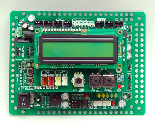 AT-BOT controller board is called the ATX board, which is able to drive 6 of DC motors and 6 of Servo motors together. It has many ports for interfacing with both digital and analog sensors, basic digital output ports and using the data communication via 2 lined bus system called I2C bus and the standard UART serial bus.
- Main microcontroller is Atmel’s ATmega128. It features 8-ch 10-bit Analog to Digital Converter, 128-KByte Flash memory , 4-KByte EEPROM, 4-KByte RAM. Operated with 16MHz clock from external crystal
- Define all ports compatible with Wiring I/O standard hardware (www.wiring.org.co). The port numbers are from 0 to 50.
- 13 programmable port in JST connector type. Includes Digital I/O port (2 :port 14 and 15), A/D port (7 : port 40/ADC0 to port 46/ADC6), Two-wire interface or TWI (2 : port 0/SDA and port 1/SCL) and UART serial port communication (2 : port 2/RX1 and port 3/TX1). Both TWI and UART ports allows you to configure the digital input/output port for more I/O applications.
- Analog input (ADC0 to ADC6) supports 0 to +5Vdc input. The converter resolution is 10-bit. The result value is 0 to 1,023 range.
- One variable resistor is connected to the Analog input ADC7 of the main microcontroller for simple ADC experiment.
- 2 button switches with pull-up resistors are connected to port 49 and 50 of the Wiring I/O controller board for simple digital input experiments.
- One LED with a current limited resistor. It is connected with port 48
- One piezo speaker at port 4
- 16x2 characters LCD for monitoring
- On-board digital compass; HMC6352 from Honeywell. It is interfaced by I2C bus or TWI
- UART port for interfacing serial module device such as camera module (ZXCCD, CMUCAM1, CMUCAM2, mCAM), servo controller board (Parallax servo controller, ZX-SERVO16U), Real-time clock (ZX-17 : serial real-time clock module)
- 6-ch DC motor driver with indicators. Support 4.5V to 9V DC motor. Maximum current output 3A and 1.2A continuous.
- 6-RC servo motor output; support 4.8 to 7.2V standard and continuous servo motor types.
- Motor driver power indicator; normally turned on. It will turn off when motor is turned off
- 5-status battery level monitor circuit :
- Last the left yellow LED displays the input supply voltage is 6.75V. When the battery voltage is lower than 6.75V, this LED will start to blink.
- Next the yellow LED displays the input supply voltage at 7.0V.
- First the green LED displays the input supply voltage at 7.25V.
- Second the green LED displays the input supply voltage 7.5V.
- Last right green LED displays that the input supply voltage is higher than at 7.75V.
- Download and interface with computer via USB port by using USB to UART converter chip; FT232RL. USB connection indicator is available.
- Set the operation by Mode/Reset switch
- Supply voltage range +7.2 to +9V 2400mA for 4 motor loads.
- 2 voltage regulator on-board; +5Vdc for microcontroller and all digital circuit, +6Vdc for all motor driver circuits. By using voltage regulator; the motor driver circuit can drives DC motor with constant speed when battery voltage is full and reduce to 60%. It features constant speed without effect by battery voltage until it is lower 60% of full.
Sorry, there are no videos available at the moment
Sorry, there are no downloads available at the moment